Introduction
The design of the NBS-200 preamplifier is fully discrete throughout the entire audio path, including the compression detector. No operational amplifiers, only transistors.
The goal was to create a so-called "finished sound," so that the sound engineer has minimal work placing an instrument into the prepared mix. When transparent sound is required, the
NBS-200 can be switched into full "bypass" mode, where all circuits affecting tonal coloration are bypassed—thus the device behaves like an (un)ordinary DI-box.
The primary intention, however, is to use the filters, saturation, and compression to achieve the desired sound. The frequency filters are designed as passive, which means
that no active components (operational amplifiers, transistors) or feedback loops are used to modify the frequency response, as is common in other designs. This results in a very relaxed,
natural sound. The HPF filter features a resonance peak at the cutoff frequency, emphasizing the given frequency. The notch filter is designed solely to "remove" unwanted frequencies.
The saturation circuit is designed so that the saturated signal is smoothly blended with the original signal, providing the sound engineer with maximum control over the tone.
The higher harmonics generated by signal saturation/limiting naturally enhance instruments that would otherwise get lost in the mix.
The compressor helps to balance the player's dynamics with the very natural behavior of the unique NBS-200 circuit design. The compression ratio varies according to the input signal level.
Compression is engaged once -15 dB is reached on the PPM meter. The compressor’s time constants can be set to three fixed values.
The level indicator displays both input level and compression level, i.e., the action of the compression detector. Input level indication is extremely fast at 1 ms—compared to 300 ms for a VU meter—
allowing any clipping to be reliably detected. The indicator is equipped with a "peak hold" mode lasting 1 second.
Technical specification NBS-200
Preamplifier / DI for Bass Guitar- Input Impedance - Instrument: 680 kΩ
- Input Impedance - Line: 10 kΩ
- Line Input Isolation / Balancing: Transformer
- Gain: 30 dB
- HPF Range: 20 to 120 Hz, 20 Hz steps
- HPF Slope: 12 dB/oct.
- HPF Type: Passive, RLC
- Band-stop Filter Range: Stepped, (200, 300, 400, 500, 700 Hz)
- Band-stop Filter Attenuation: Continuously adjustable, 0 to -10 dB
- Band-stop Filter Type: Passive, RLC
- Saturation: Continuously adjustable level, parallel path
- Saturation Type: J-FET
- Compression - Threshold: -15 dB
- Compression - Ratio: 2:1 to 10:1
- Compression - Type: Diode bridge
- Compression - Attack/Release: 3 fixed positions
- Output Level: 0 dB = +4 dBu
- Output Limiting at: +8 dBu
- Output / Balancing: Transformer
Block Diagram and Description
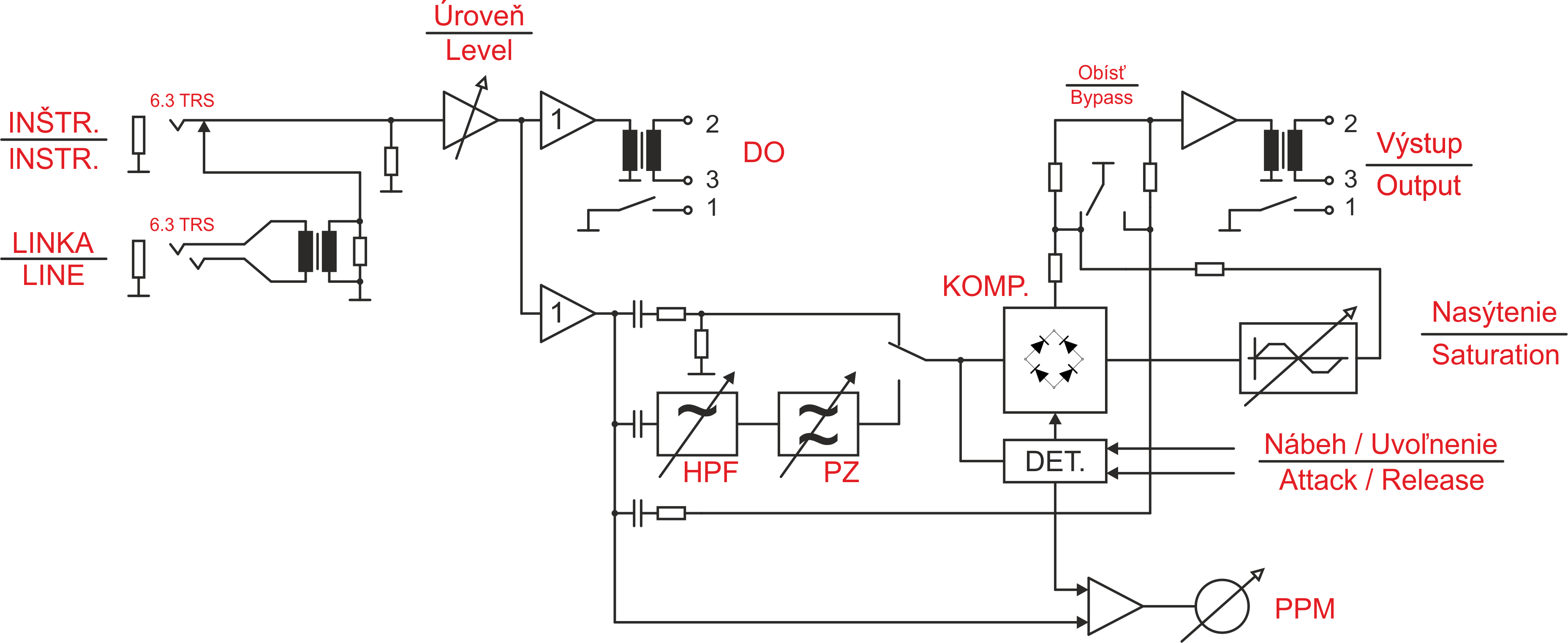
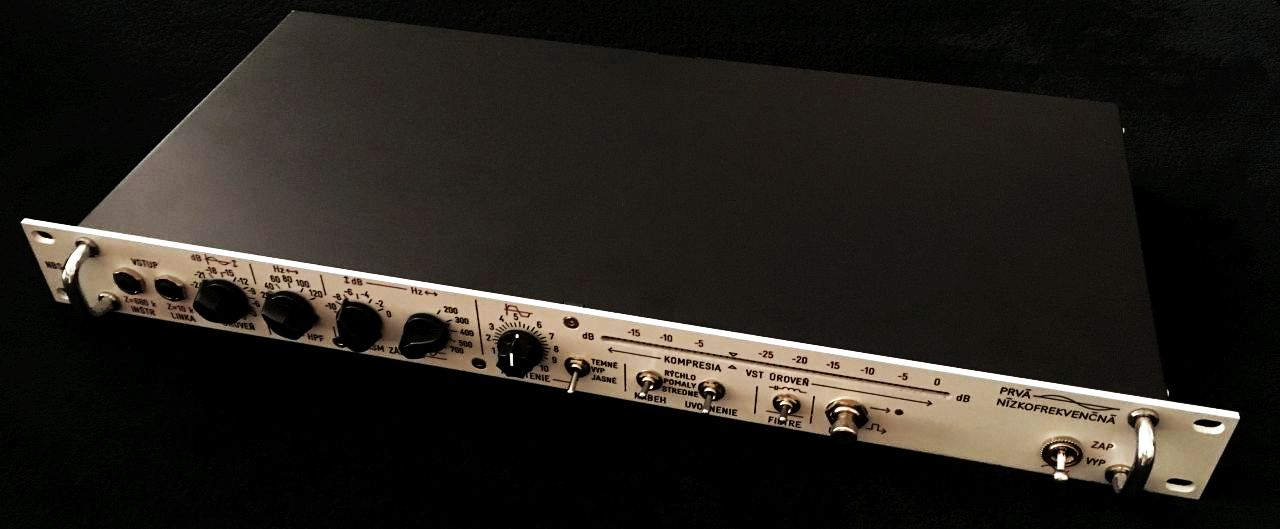
The device input consists of two TRS 6.3 mm JACK connectors: one for Instrument (no. 1) and one for Line (no. 2). The Instrument input has priority, so when an instrument cable is plugged into the INSTR. connector, the LINE input is automatically deactivated.
Next comes the gain stage and level control (no. 3). The level is adjusted in 3 dB steps. This ensures precise and repeatable settings. When the filter switch (no. 11) is activated, the signal can be adjusted using the HPF filter (no. 4) in 20 Hz steps, with the cutoff frequency emphasized. The HPF slope is 12 dB/oct. or 40 dB/dec. Following this stage is the Band Stop section, where the desired frequency can be selected with switch no. 6 and its attenuation smoothly adjusted with control no. 5.

The saturation circuit adds harmonic components to the original signal, desired for presence or intentional distortion. It is activated with switch no. 8 and can be smoothly blended with the original signal using potentiometer no. 7.
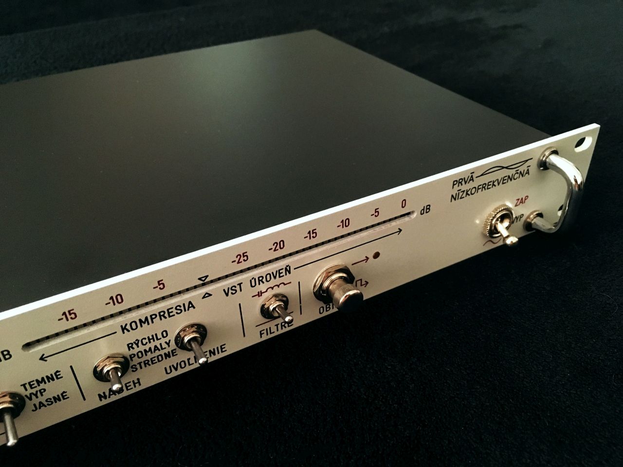
The compressor engages at -15 dB on the PPM indicator (no. 14). Switches no. 9 and no. 10 adjust the peak detector ballistics, thereby setting the compressor’s response to the input signal. The compressor reacts very naturally. Due to its circuit design, it slightly colors the signal, making it suitable for a fairly universal range of applications, including vocals and drums.
With switch no. 12, the entire effects section can be bypassed, sending only the clean source signal to the output.
The main power switch (no. 13) turns the unit on/off. The startup sequence consists of gradually lighting all 50 LED segments while the transistor operating points stabilize. Once the sequence is complete, the device is ready for operation.
Photos


Sound
Instrument: Fender Jazz Bass. The recording levels were only normalized, with no additional post-processing.
DAW: Reaper, 44.1 kHz / 24 bit.
The sound was captured from both NBS-200 outputs simultaneously: the regular output and the DI output,
which is permanently unaffected. See the block diagram above.
A) HEAVY 1 - Effect output NBS-200.
HPF: 40 Hz, PZ: 500 Hz @ -6 dB, Saturation: 2 o’clock, Attack: Medium, Release: Slow
B) HEAVY 1 - DI output NBS-200.
Only amplification, no other circuitry affecting the signal path.
***
C) WALK - DI output NBS-200.
Only amplification, no other circuitry affecting the signal path. Essentially DI mode.
D) WALK - Focusrite Scarlett.
For comparison, the instrument input on the Focusrite Scarlett 18i8.
***
E) SLAP - DI output NBS-200.
Only amplification, no other circuitry affecting the signal path. Essentially DI mode.
F) SLAP - Focusrite Scarlett.
For comparison, the instrument input on the Focusrite Scarlett 18i8.
***
G) HEAVY 2 - Effect output NBS-200.
HPF: 40 Hz, PZ: 500 Hz @ -6 dB, Saturation: 2 o’clock, Attack: Medium, Release: Slow
H) HEAVY 2 - DI output NBS-200.
Only amplification, no other circuitry affecting the signal path.
Video of NBS-200 sound: